Introduction
The BrightEyes-TTM project [1] born as an offshoot of the BrighEyes project founded by the ERC in 2018 (Consolidator Grant, N. 818699). The principal aim of the BrightEyes-TTM project is to give to any microscopy laboratory the possibility to implement and further develop single-photon microscopy. The second aim is to trigger the interest of the microscopy community, and establish the BrigthEyes-TTM as a new standard for single-photon laser scanning microscopy (LSM) experiments.
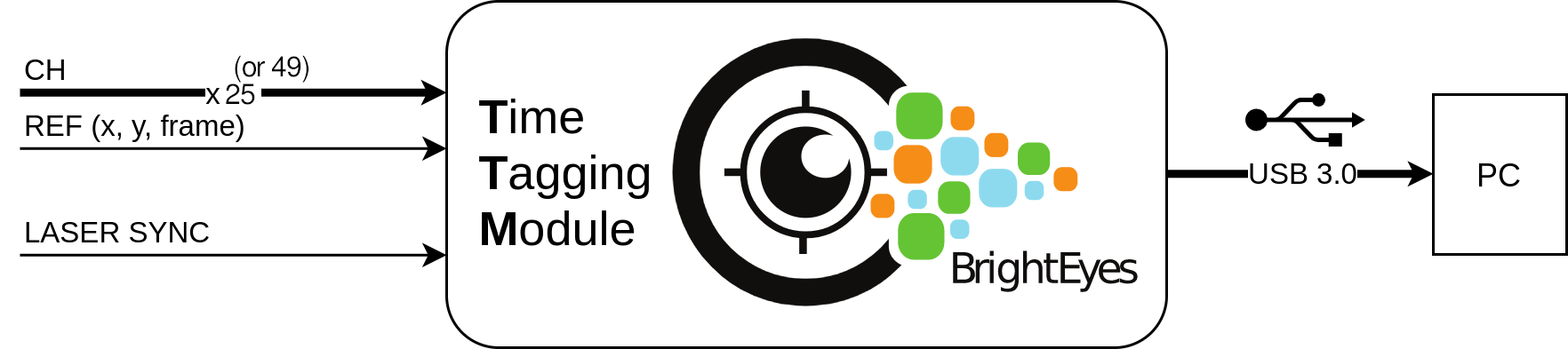
Fig. 1 - The BrightEyes Time-Tagging Module
Note
In this documentation you can find everything you need to build and further modify the BrightEyes-TTM in your lab.
The source code, the open hardware, python libraries and example are available in GitHub at the following address: github.com/VicidominiLab/BrightEyes-TTM version 2.0
Note
There are two version of BrightEyes-TTM. The article on arXiv is referred to the version v1.0, the article published is refered to the version v2.0.
The legacy version (v1.0) is available in the branch on GitHub github.com/VicidominiLab/BrightEyes-TTM version 1.0
The BrightEyes-TTM mainly consists in a data-acquisition (DAQ) card able to implement the so-called photon time-tagging acquisition mode (Fig. 2).
Note
Article on Nature Communications: Rossetta, A., Slenders, E., Donato, M. et al. The BrightEyes-TTM as an open-source time-tagging module for democratising single-photon microscopy. Nat Commun 13, 7406 (2022). https://doi.org/10.1038/s41467-022-35064-0
Time-tagging
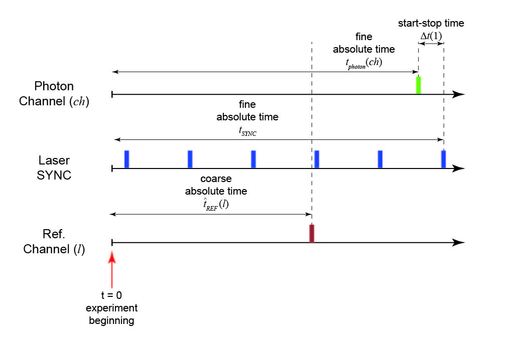
Fig. 2 - Time-tagging principle.
The time-tagging (TT) mode allows recording individual events and labelling each of them with a temporal signature. Typically this temporal signature denotes the delay time of the events in respect to the beginning of the experiment (absolute time). The BrightEyes TT module (TTM) is able to tag three different class of events: The photon events, i.e., a photon is registered by the detector which delivery a digital signal to the module; The sync laser events, i.e., the synchronisation signal delivered by a pulsed laser; the reference events, i.e., a signal generated by another component of the experimental setup (e.g., an actuator, a laser modulator). Starting from these temporal signatures it is possible to derive many other different temporal information. For example, for each photons event it is possible to derive the so-called start-stop time, which describe the delay of the photon event in respect to the successive sync laser event. Very important, together with the temporal signatures, the BrightEyes-TTM records also the number of the channels ( ch ) or inputs ( l ) associated to the photon or reference event. In the single-photon laser microscopy applications of our BrightEyes-TTM, the channel for the photon event describes the element of the single-photon-avalanche diode (SPAD) array detector which collected the photon, thus it can be considered a spatial signature.
Main components
The BrightEyes-TTM is based on a field-programmable-gate-array (FPGA), which allows implementing a series of time-to-digital converters (TDCs), i.e., the building block of the TTM. Current BrightEyes-TTM implementation allows to temporally tag single-photon events with respect to the laser sync (i.e., the start-stop time) - with 30 ps precision - and the reference events (such as pixel, line and frame signals) - with 4.2 ns precision. Because the BrightEyes-TTM is a VHDL/Verilog-based open-access project, it can be upgraded, modified, and customized by all the microscopy-makers.
The TTM can transfer data to a personal computer (PC) via USB 3.0 cable and can be connected to a fluorescence LSM setup, as a passive plug-n-play device, thanks to a custom interfacing connector board. As shown in the data processing examples below, the BrightEyes-TTM allows for fluorescence spectroscopy, fluorescence lifetime imaging microscopy (FLIM) [2], and for fluorescence lifetime correlation spectroscopy (FLFS) experiments [3]. More in general, the TTM can be used to fully explore the great momentum in the development of new bi-dimensional or one-dimensional asyncronous read-out SPAD array detectors [3,4].
The BrightEyes-TTM is composed by three main parts: the FPGA evaluation board (Xilinx® KC705 Evaluation board); the FX3 data transmission chip (EZ-USB® FX3™ SuperSpeed Explorer Kit and FMC Interconnect Board for the EZ-USB® FX3™ SuperSpeed Explorer Kit); a custom-made I/Os SMA-FMC daugther connector card. The three part need to be assembled (Fig. 3) following the instruction below (expand the Assembly Instuctions). Both the FX3 data transmission chip and the I/Os FMC daugther card easily interlock to the main Xilinx® FPGA board.
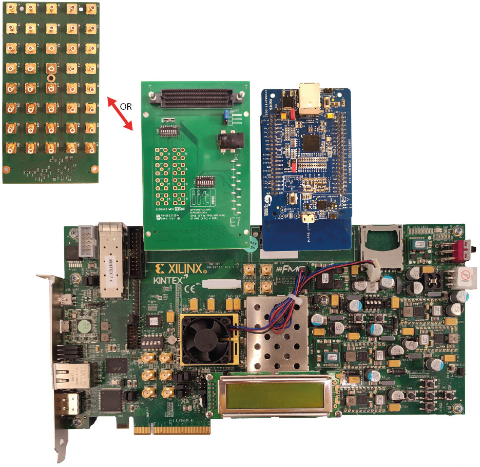
Fig. 3 - BrightEyes-TTM assembly.
Specifications
Single shot precision * |
30 ps |
Time bin width |
user defined (default 43 ps) |
Time range ** |
not limited by hardware |
Maximum laser sync rate |
80 MHz |
Dead time |
1 / 240 MHz = ~ 4.2ns |
Differential non-linearity |
~ 6 % RMS |
Input channels with 30 ps precision |
21, 25, (49 under testing) |
Input channels with < 4.2 ns precision |
3 |
Laser SYNC channels |
1 |
* Gaussan fitting sigma value
** Tested at 200 ns (5 MHz), 100 ns (10 MHz), 50 ns (20 MHz), 25 ns (40 MHz), 12.5 ns (80 MHz)